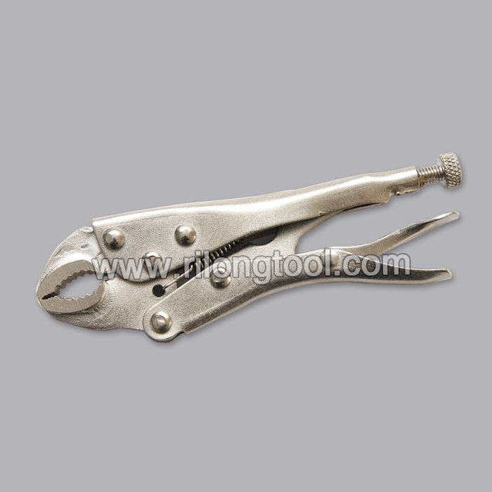
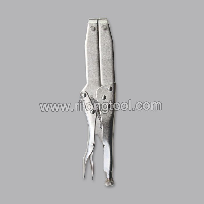
factory customized 6.5″ Backhand Long-nose Locking Pliers with Jackets Ethiopia Factory
Short Description:
Product Detail
Product Tags
We always stick to the principle "Quality First, Prestige Supreme". We are fully committed to providing our clients with competitively priced quality products, prompt delivery and professional service for factory customized 6.5″ Backhand Long-nose Locking Pliers with Jackets Ethiopia Factory, We sincerely look forward to hearing from you. Give us a chance to show you our professionalism and passion.
Basic Information
■Model Number: RL-DLQ014
Additional Information
■Material: A3# steel (Q235) or 45# steel
■Size: 6.5”
■Surface Treatment: Nickel-plated, Zinc-plated, Black Oxide, Electrophoresis
■Heat Treatment: Optional
■Package: Blister Card, Suction Card, Tie Card, Double Blister Card
■OEM: Acceptable
■HS Code: 8203200000
■Samples: For FREE
■Delivery Time: Always 30 working days depending on the order quantity
■Packing: By standard cartons
Product Description
■Mainly used for clamping parts to rivet, weld, grind and so on, which is characterized by the powerful clamp force produced by the jaw. It can lock tight so that the parts won’t fetch away. Besides, jaws have a lot of levels to adjust for the use of different thickness of parts, and it also can be used as a wrench.
■Flexible using, long life and good tenacity.
■The screw tuning button can give the best clamp size easily.
Product Image
These European high-grade bolt cutters-D1144030 provide a strong and effective tool that will make a useful addition to any toolbox. The long handles and high pivot point means that minimal force and effort is required in order to achieve optimal performance. The handles are aligned for accuracy and precision, whilst the jaw and blades have been designed to allow cutting close to the surface. This particular pair of bolt cutters is a size of 48″ or 1200mm.
BLOG ARTICLE: https://blog.bavauto.com/14459
“Like” us on Facebook – https://www.facebook.com/BavarianAutosport
“Follow” us on Twitter – https://www.twitter.com/BavAuto
“Subscribe” to us on YouTube – https://www.youtube.com/BavarianAuto
Visit our online store – https://www.bavauto.com/
All of the items shown in these videos are available in our online store at https://www.bavauto.com/. Need additional tech help? Please visit our tech blog for thousands of Tech and DIY BMW and MINI articles at: https://blog.bavauto.com/
—
In Part-2 of this two part series, we will install the front steering tie-rod on a typical BMW with rack and pinion steering. We will be using an E30 3-series (84-91), but these general procedures will apply to most models that have the rack and pinion type of steering system. See Part-1 for the removal.
The Bentley repair manuals will cover standard tie-rod replacement for the various BMW and MINI models. This DIY will assume that the DIYer has the applicable Bentley manual for additional reference as well as fastener torque values.
PARTS USED:
• Tie-Rod (complete, inner & outer)
• Rack boot
• Rack boot clamps (2)
• Tie-rod inner lock plate
TOOLS USED:
• Bentley Repair Manual
* Tie-rod inner end removal tool
* Tie-rod outer end removal tool (press)
* Boot pinch-clamp pliers
* Safe-Grip gloves
* 3/8″ drive ratchet or breaker bar (for inner tie-rod end removal tool)
* Various 3/8″ and/or 1/2″ drive sockets and ratchet (13mm through 22mm, depending on model)
* Various 13mm through 22mm combination wrenches, depending on model.
* Hammer
* Flat-blade screwdrivers and/or cold-chisels
* Diagonal or end/flush cutters
NOTE: In this DIY, we will be replacing the complete tie-rod assembly (as opposed to just replacing the inner or outer joint). We find this preferable as it is typically easier and while only one end (inner or outer) may be worn-out, the other end is likely near the point of wear-out.
INSTALLATION PROCEDURE (see part-1 for removal):
9) Place the old tie-rod and the new tie-rod assembly on the workbench, side-by-side. Compare the length from the flat face of the inner joint housing (where it mates with the end of the rack) to the center of the outer joint spindle pin. Adjust the new assembly to match the length of the old assembly. DO NOT adjust to the end of the outer joint housing as the casings could be of slightly different sizes. Measure/adjust to the center of the spindle pin.
10) Once adjusted, tighten the adjustment locking clamp or sleeve nut (depending on the application). This adjustment will allow the vehicle to be driven until an alignment can be performed (front toe adjustment), without excessively wearing the tires.
11) Install the new rack boot over the inner tie-rod end and push the boot down the tie-rod so that it clears the inner joint.
12) Install a new lock-plate on the inner tie-rod end (over the threaded end). Note the tab that mates into the cut-out in the end of the rack. Be sure to install the lock-plate so that the tab properly engages into the rack’s cut-out.
13) Thread the inner tie-rod end into the end of the rack. Make sure the lock-plate tab aligns with the rack’s cut-out (as noted in step-12). Use the thin wrench or the inner tie-rod tool to tighten the tie-rod’s inner end to the rack.
14) Use a hammer to bend the lock-plate over the two flats on the inner tie-rod housing.
15) lightly coat the spindle pin of the outer tie-rod end with the Liqui-Moly anti-seize compound. Insert the spindle pin into the receiving eye on the steering knuckle or steering arm. Lightly tab the tie-rod end to seat the spindle pin into the eye. Install and tighten the spindle pin nut. If the spindle pin turns while attempting to tighten the nut, tap the pin into the eye with a bit more force or place a jack under the end and apply upward pressure on the spindle and eye. Torque the nut to the value specified in the Bentley manual.
NOTE: Most applications use a lock-nut on the outer joint spindle pin. In these cases ALWAYS use a new nut. Some older applications may use a castellated nut and a cotter-pin. In these cases, ALWAYS use a new cotter-pin.
16) Seat the rack boot over the end of the steering rack outer housing and the mount bushing on the tie-rod. Install the two pinch clamps. Pinch the clamps using the pinch clamp pliers.
17) Lower the vehicle. and arrange to have the front toe adjusted as soon as possible.
——–
All products noted in this video can be purchased in our online store, https://www.bavauto.com/, 24 hours a day, 7 days a week. You are also welcome to e-mail us at info@bavauto.com or call into our headquarters and speak to our knowledgeable advisors at (800) 535-2002 (Mon.-Thurs. 8AM to 9PM EST, Fri. 8AM to 7PM EST, and Sat. 9AM to 4PM EST).


